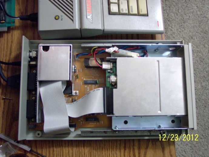
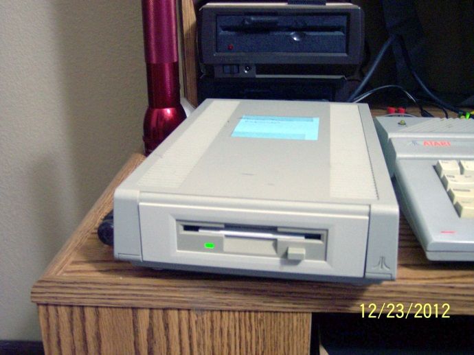
Finished the conversion of my XF551 from 5 1/4 to a 3 1/2 inch drive.
I took me awhile to find the answers on how this upgrade was done (I even had to guess at some of it). I wanted these instructions to be at the top of a thread instead of buried in the middle of another, just in case someone else wanted to create one of these "novelty" items.
I CANNOT STRESS THIS ENOUGH!!! THE XF551 PCB IS A SINGLE SIDED PCB AND IS VERY FRAGILE. OVERHEATING WILL CAUSE TRACES TO BREAK.
If you are not handy with soldering tools, leave it to professionals. These instructions are written for professionals. If anything in here confuses you, stop and get help.
Parts Needed
1 28 pin wide socket (Only if U6 does not have a socket already in it)
1 longer floppy cable with IDC connector (optional additional card edge connector for the purpose of returning to the original mechanism or dual mechs, not covered here)
1 Molex to 4 pin floppy power adapter
1 2764 eprom programmed with the new XF551 rom (lots of places to download).
1 5 1/4 to 3 1/2 inch drive mounting adapter.
Tools
Soldering Iron (30 watts max, I use a 15/30 watt)
Desoldering Item (desoldering plunger, desoldering iron (30 watts max, my preference) or desoldering wick)
Needle nose pliers
Phillips screwdriver
Precision flat head screwdriver
IC Remover
I will not go through the mundane steps of taking apart the XF551 as it is pretty self evident, take all the screws out. There is one screw that is the exception. There are 4 screws to remove the PCB. 3 are easily visible. The 4th is located under the heat dissipator and there is a hole provided to reach it. Getting it out is easy enough, but putting it back, I used a magenetic screwdriver.
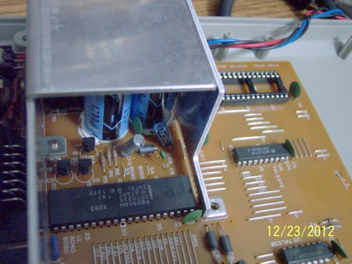
First look at U6 on the PCB. I imagine there are 4 possibilities.
1. It is empty. Your drive is using the "internal" OS. You will need to desolder the holes of U6 then solder in a 28 pin wide socket.
2. There is an empty 28 pin socket. Your drive is using the "internal" OS.
3. There is a 28 pin IC soldered to the PCB. Your drive uses the "external" OS. You will need to desolder the IC in U6 and then solder in a 28 pin wide socket.
4. There is a 28 pin IC mounted in a socket. Your drive uses the "external" OS. You only need to remove the IC from the socket.
In all cases, your programmed 2764 goes in this socket and will be used as an "external" OS.
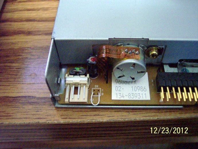
Next look near the 40 pin IC. There are two jumpers (a wire over the PCB) labeled S3 and S4. These decide whether you are using an "internal" OS (S4 jumped, S3 empty) or an "external" OS (S3 jumped, S4 empty). With the upgrade being an "external" OS, S3 needs to be jumped and S4 needs to be empty. If S4 is jumped, you can remove it and use it to jump S3. To remove with the best possible results, use your precision flat head screw driver to straighten each end of the jumper pins while heating it with your soldering iron. Let it cool completely, then use the desoldering tool of your choice and remove. Resolder it in S3.
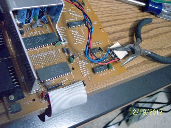
Replace ribbon cable.
A. Using the precision screwdriver, unlock each side of the plastic crossbar of the IDC connector that is soldered onto the XF551 PCB. Do this next to the PCB, it cannot be done from the top.
B. With the crossbar removed, take note of where pin one is by the colored line of the cable. Use the precision screwdriver to carefully lift the ribbon cable from the IDC connector starting at one end and slowly moving to the other.
C. When attaching the new ribbon cable, I do not reccomend using a squeeze method (vise) using the crossbar. The XF551 PCB is so fragile, I would not be surprised to see it break if this method were used. Line the new longer cable up with pin one (you took note of this above). I used a pair of needle nose pliers to gently push the ribbon cable itself onto the connector, layin each side of the pliers on either side of the pins to give me even pressure. You must have patience when doing this. Then I placed the crossbar on as a cap.
Mount the completed the PCB in to the case (rememberthe screw I mentioned above?).
The XF551 drive requires the drive mechanism to be jumped as drive 0. All modern 3 1/2 inch PC drives are jumped as drive 1 permanently, but usually have a way to solder a wire to jumper it as drive 0. You will need to consult the manufactuer's specs and make it a drive 0 mech.
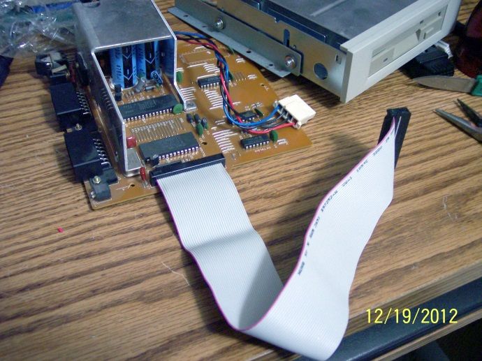
Mount the 3 1/2 inch drive in your mounting adapter. Remove the XF551 mechanism mounting rails from the 5 1/4 inch drive and attach them to the 3 1/2 inch mounting adapter. Mount this assembly to the drive case. Attach the new ribbon cable and the power adapter to the drive.
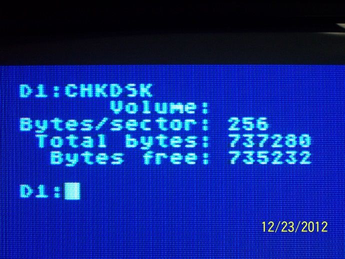
Plug in your computer and test with Sparta DOS.
Test Successful, reassemble case.
![Posted Image]()
![Posted Image]()
![Posted Image]()
![Posted Image]()
![Posted Image]()
![Posted Image]()
![Posted Image]()
I took me awhile to find the answers on how this upgrade was done (I even had to guess at some of it). I wanted these instructions to be at the top of a thread instead of buried in the middle of another, just in case someone else wanted to create one of these "novelty" items.
I CANNOT STRESS THIS ENOUGH!!! THE XF551 PCB IS A SINGLE SIDED PCB AND IS VERY FRAGILE. OVERHEATING WILL CAUSE TRACES TO BREAK.
If you are not handy with soldering tools, leave it to professionals. These instructions are written for professionals. If anything in here confuses you, stop and get help.
Parts Needed
1 28 pin wide socket (Only if U6 does not have a socket already in it)
1 longer floppy cable with IDC connector (optional additional card edge connector for the purpose of returning to the original mechanism or dual mechs, not covered here)
1 Molex to 4 pin floppy power adapter
1 2764 eprom programmed with the new XF551 rom (lots of places to download).
1 5 1/4 to 3 1/2 inch drive mounting adapter.
Tools
Soldering Iron (30 watts max, I use a 15/30 watt)
Desoldering Item (desoldering plunger, desoldering iron (30 watts max, my preference) or desoldering wick)
Needle nose pliers
Phillips screwdriver
Precision flat head screwdriver
IC Remover
I will not go through the mundane steps of taking apart the XF551 as it is pretty self evident, take all the screws out. There is one screw that is the exception. There are 4 screws to remove the PCB. 3 are easily visible. The 4th is located under the heat dissipator and there is a hole provided to reach it. Getting it out is easy enough, but putting it back, I used a magenetic screwdriver.
First look at U6 on the PCB. I imagine there are 4 possibilities.
1. It is empty. Your drive is using the "internal" OS. You will need to desolder the holes of U6 then solder in a 28 pin wide socket.
2. There is an empty 28 pin socket. Your drive is using the "internal" OS.
3. There is a 28 pin IC soldered to the PCB. Your drive uses the "external" OS. You will need to desolder the IC in U6 and then solder in a 28 pin wide socket.
4. There is a 28 pin IC mounted in a socket. Your drive uses the "external" OS. You only need to remove the IC from the socket.
In all cases, your programmed 2764 goes in this socket and will be used as an "external" OS.
Next look near the 40 pin IC. There are two jumpers (a wire over the PCB) labeled S3 and S4. These decide whether you are using an "internal" OS (S4 jumped, S3 empty) or an "external" OS (S3 jumped, S4 empty). With the upgrade being an "external" OS, S3 needs to be jumped and S4 needs to be empty. If S4 is jumped, you can remove it and use it to jump S3. To remove with the best possible results, use your precision flat head screw driver to straighten each end of the jumper pins while heating it with your soldering iron. Let it cool completely, then use the desoldering tool of your choice and remove. Resolder it in S3.
Replace ribbon cable.
A. Using the precision screwdriver, unlock each side of the plastic crossbar of the IDC connector that is soldered onto the XF551 PCB. Do this next to the PCB, it cannot be done from the top.
B. With the crossbar removed, take note of where pin one is by the colored line of the cable. Use the precision screwdriver to carefully lift the ribbon cable from the IDC connector starting at one end and slowly moving to the other.
C. When attaching the new ribbon cable, I do not reccomend using a squeeze method (vise) using the crossbar. The XF551 PCB is so fragile, I would not be surprised to see it break if this method were used. Line the new longer cable up with pin one (you took note of this above). I used a pair of needle nose pliers to gently push the ribbon cable itself onto the connector, layin each side of the pliers on either side of the pins to give me even pressure. You must have patience when doing this. Then I placed the crossbar on as a cap.
Mount the completed the PCB in to the case (rememberthe screw I mentioned above?).
The XF551 drive requires the drive mechanism to be jumped as drive 0. All modern 3 1/2 inch PC drives are jumped as drive 1 permanently, but usually have a way to solder a wire to jumper it as drive 0. You will need to consult the manufactuer's specs and make it a drive 0 mech.
Mount the 3 1/2 inch drive in your mounting adapter. Remove the XF551 mechanism mounting rails from the 5 1/4 inch drive and attach them to the 3 1/2 inch mounting adapter. Mount this assembly to the drive case. Attach the new ribbon cable and the power adapter to the drive.
Plug in your computer and test with Sparta DOS.
Test Successful, reassemble case.