After some days I've Been working on this.
For years I want to make this Dot Matrix Display.
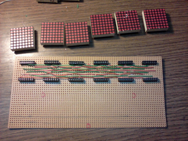
I'm going do the first tests on basic. I know... it is to slow, but, is just for testing. ![]()
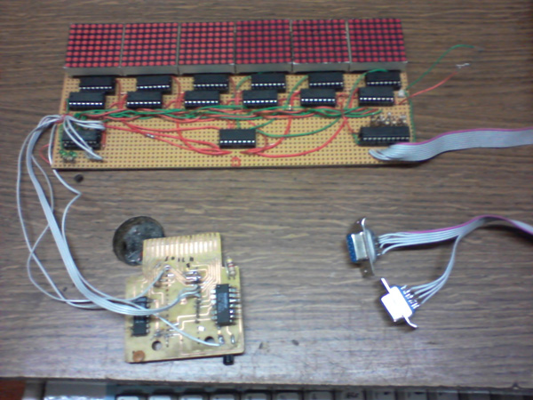
The heart of this operation is a decoder (74LS259) chip , which allow me select between 8 outputs. This outputs manage a bunch of serial shift registers chips (74LS595): Serial Input, Output Enable, Latch, Clock and Reset. The state of each are controlled by the Atari itself (no other processor needed).
So, the idea is showing text, scroll text, and frames (some animations). What for? I'm going to use it in a pinball machine that I building.
Tech stuff
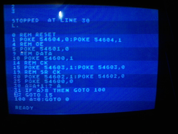
This kind of matrix displays working more than less at the same way: They drive on column at the time meanwhile they send the data to the row. On my design I have 8 serial shift register in chain to do that, RST clear all outputs, OE Enable or disable all outputs, Latch keep the data, CLOCK advance one step, SERIAL IN must be 1 at the first step, but immediatly must be 0, or every colums are 1 in 48 clocks (that is very bad). The idea is drive just one column at the time, from right to left. The ROW data come from the joystick port, so we have to set them as OUTPUT POKE 54018,43 (must set just at the start ) and the data we want to send POKE 54016,DATA
The decoder 74LS259 are managed this way:
when a adress between 54600~54608 are POKEd the cartridge line CCTL are activated, and in conjunction with the clock signal O2 (NAND) makes the chip are Enabled. So, if we did POKE 54600,1 A0=0 A1=0 A2=0 then output Q0 (pin 4) is selected and the data we send, in this case 1, are carry to this pin. This chip have latch, so the state remains stored until we change it.
For last, every column must be drived by one ULN 2003 chip. And every ROW with a 220 ohms resistor. I pass the ROWs data thru an 74LS245 buffer chip, to protect the PIA.
Schematic: